JJMA :: Lighting Up Plastic Models
Way back in middle school, a good friend and I came up with an idea. At that time,
we were both into building plastic models. My friend, who I won't mention by name, as
I have not asked him for permission to do so yet, was an excellent painter and had some
beautiful models. I had toyed with putting lights in plastic models, and had some prototypes,
but no finished products. (Most of the models I had built were hastily assembled, as I was
not good at taking my time.) Together, we formed a club. I imagine most people
have a "making a club" story in their childhood. Our club was a model-building club that
made Star Trek models. (Why Star Trek models?) Well, we got a
few other members, but really it came down to just him and I. We built our first model in
1993: a Klingon Cruiser.
When we were starting out, we would go to one another's houses and spend the night
working on models. The goal was to see if we could finish a ship in a night. Later, it was to
finish more than one in a night. This led to working on models before "meetings". Three
ships at once was the most ever completed a single night. Now, it's 10 years later. We still
have that first Klingon Cruiser and many others. We still build ships on the average of
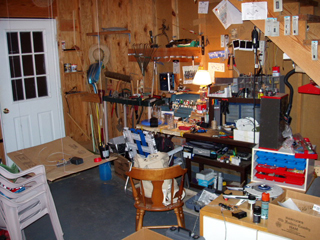
one a year. There are a total of 40 ships that have been made. 32 are functional today and
hanging in my mother's (graciously donated) garage. 2 others have been given to other
caretakers. (Sadly, I don't have digital pictures of these 2.)
This question is pretty easy to answer. At the time, they were readily available and cheap.
(We were doing this with out allowances then!) The Star Trek model kits had a lot of open
space in them making them ideal for wiring. Many people will criticize that the Ertl models are
not terribly accurate, but we were really looking for a good time. I think we had the most fun
building custom ships with lights and configurations of our own designs. Also, "correct"
replacement parts are usually resin. Resin is not a very good medium for light-ups.
All of the models we have built have been AMT/Ertl plastic models. They are simply
polystyrene models.
None of the kits were designed with lighting in mind, though many
came with clear plastic parts. To make these models, we took a kit and drilled holes in it.
In those holes and in the depth of the models, we fitted LED lights and bulbs. Most of the
models are powered by a pair of D-Cell batteries, but some are 9V models.
LED lights, in case you don't
know, are small solid-state lights, like little green
light on your computer monitor. Each model has a wide collection of these lights in
varying colors. Sometimes, small wheat bulbs are used, but we try to avoid using them for
two reasons: 1. power consumption. 2. bulb life. Often, "running lights" flash with the aid of an
LM3909 LED flasher chip. (This chip is no longer manufactured.) Each model is wired to a
control panel,
that controls sections of lights on the model forming
systems. For example,
all lights relating to propulsion, or weapons, or running lights, will be grouped
and given their own switch.
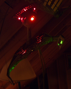
|
A few models after minor repairs
|
Models used to have classifications relating to how many of these systems they had. There
were 4 such classifications: A, B, C, and X. These were nick-named Alpha, Beta, and "Ceta".
(Keep in mind, we were kids. We are well aware there is no "Ceta".) C referred to a model
with 1-2 systems. 3-5 was Beta. 6-9 was Alpha. X was anything exceeding 10. Usually, a model
was given a number code with the year, the number for that year and class. For example,
the 3rd model of 1999 with 5 systems would be 0397BA. The final "A" denotes action model,
that is, a model without a stand. "S" would denote a model with a stand. A final "X" would
denote that it was the first time we built such a model. Many of these denotations have been
forgotten with time. Often, such information was written inside the models, but breaking them
open to get at this info would not be in our best interests.
We used an 8-conductor telephone cable to link the model to its power supply. The first
model we built in 1993 used this as 4 power / ground pairs. Not very efficient, so for the second
model, we used one ground wire. This practice of using one ground wire became standard,
even for models with multiple power supplies. (This is referred to as
common ground.
Earlier models would use separate grounds for 9V and 3V, but they are integrated now.) This
allowed us 7-systems with one wire. Modern models use this same system, but a pair is reserved
for running lights, as we do not put the LED-flasher inside the model anymore. This is so we
can service the flasher if needed and conserve space inside the model. (5-systems and
one flasher source) Some models have more than one wire (such as X-classes). However, having
as few wires as possible was the goal, as they are unsightly.
Right now, we are developing new flashers to replace the LM3909. The 555 timer is a widely
available chip and is being considered in CMOS form.
Control panels evolved also. There are 3 basic styles, which I will call by generation.
Generation 1 was a sturdy plastic / aluminum box that was fitted with indicator lights and toggle
switches. These control panels are arguably the most attractive and strongest panels that we built.
They were also the most expensive. Toggle switches cost a few dollars apiece.
So, a control panel for a 5 system model would need 6 switches (one is a power switch), a case,
a battery holder, and 6 indicator lamps. This would total around $25 dollars or more. A plastic model
would cost about $10 plus maybe $12 worth of lights and resistors.
Generation 2 control panels were designed for one thing: to be cheap. These control panels
were only circuit-boards with indicator LEDs and slide-switches soldered to them. These control
panels proved delicate and failure-prone.
Generation 3 control-panels are a sort of hybrid of the other generations: These control panels
use a breadboard that is drilled and slotted to hold slide-switches. (A Dremmel Rotary Tool is the
cutter of choice for this.) The slide-switches are held in place with screws. Indicators are
LEDs with plastic ring holders. The wire leading to the model is attached with a screw panel, so
the model can be removed from the control panel easily. This model is far cheaper than Gen. 1,
but far sturdier than Gen. 2. It is also fairly attractive.
Well, this is more complex than it used to be, but these are the basic steps.
1. inspect the model and plan what to do.
2. ensure that you have all LEDs and resistors that will be needed.
3. Drill the hull of the model for LED mounts and Internal lighting.
4. Spray-paint the interior and exterior. Gloss Black is best for the inside to prevent light leaks. Glue any breadboard mounts that will be needed to the plastic after the paint drys.
5. mount all LEDs and glue them into place.
6. Wire all lights together into systems. Test as you go. Once all systems are wires, link their grounds.
7. run the wire to link the controls and the systems. Cover all exposed connections.
8. Finish basic detail painting.
9. Test fir the model together and ensure all systems stay functional (no shorts).
10. glue. Finish the control panel while you wait for the glue to dry.
11. touch up paint.
Ok, this is a really basic list. On a model with 5 systems (say about 30 LEDs), this should take you
about a week to do a quality job. It's like art: no two models are the same. The Panning stage and the
wiring stages are the most important. A good amount of wire is going to be crammed into a little
plastic hull!
I plan to put up photos of the individual models here, as well as a brief description of each model,
as time allows. I will try to get some more detailed information up, also.
Draft Version of Movie Era Federation Ships Posted
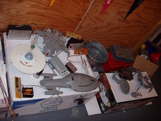
|

Quite a few models...
|